A very popular tilt detector nowadays is the accelerometer installed in our smartphones and tablets: thanks to it, every time we rotate the screen, the display changes from portrait to landscape mode and vice versa. Even with Arduino it is possible to detect the inclination of an object and in some way react to it (by reversing the direction of travel of a stepper motor or by rotating the angle of a servo motor for example); one of the simplest sensors to manage in this sense is the tilt switch, also called tilt ball switch.
What is a tilt ball switch
The tilt ball switch (or tilt switch) is a cylindrical sensor, or in any case hollow, in which a mass inside it has a certain space to move. At one end of the sensor there are two poles not in contact with each other, capable of conducting electricity. If these poles are touched by the moving mass (usually a metal sphere), the circuit closes, passing the electric current. It is not a very precise sensor, but very often its working mechanism is sufficient for most projects with Arduino. Let’s think for example of a robot or a car that must warn with an alarm when it reaches a critical inclination point.
On the other end of the sensor, on the other hand, two pins extend which are useful for connection to a breadboard or with a jumper cable (or in any case for connection to any circuit).
Here’s what the tilt switch looks like:
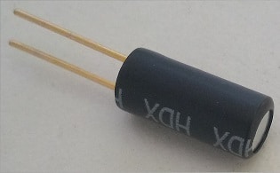
Try to rotate it to feel the mass inside it.
In this article, we will modify the sketch used to sound an active buzzer, to cause an alarm to go off if the tilt sensor is tilted.
The necessary material and the test circuit
To assemble the alarm start circuit via the tilt ball switch, we will need:
- a tilt ball switch or tilt sensor
- an active buzzer
- a breadboard
- two jumpers obtained from a twisted pair
- two male-male jumper cables (preferably of different colors)
- two male-female jumper cables (preferably of different colors)
- an Arduino board
- a usb cable to connect Arduino to the pc
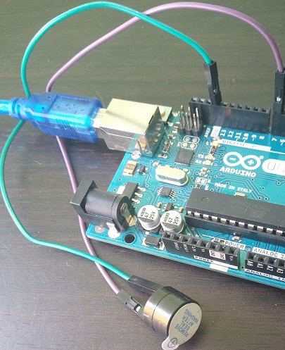
Here’s roughly what the final circuit looks like:
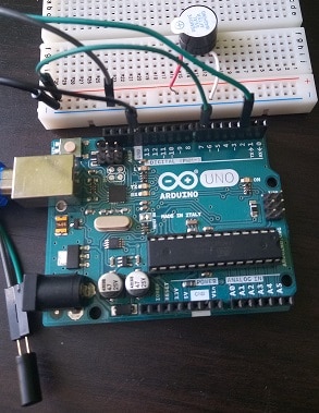
A jumper cable connects the negative line of the breadboard (visible by the minus sign) to the GND grounding pin of the Arduino, while another jumper connects pin 7 to the positive line (visible by the plus signs).
The red and white jumpers connect the positive and negative poles of the buzzer to pin 7 and to the negative channel of the breadboard.
Finally, the green male-female jumper cable connects one terminal of the tilt switch to pin 2 and the black cable connects the other terminal to ground.
The test sketch
The listing is almost completely identical to the active buzzer management program, with the difference that we define the pin connected to the tilt ball switch and modify the function sounds by inserting the reading of the value from the same pin at the beginning of the instruction block:
void sounds () {
  int digitalVal = digitalRead (PIN_TILT);

  Serial.print ("PIN_TILT outside the while loop:");
  Serial.println (digitalVal);

  while (digitalVal == HIGH) {

    frequency_1 ();
    frequency_2 ();

    digitalVal = digitalRead (PIN_TILT);

    Serial.print ("PIN_TILT inside the while loop:");
    Serial.println (digitalVal);

  }
}
The while loop is no longer an infinite loop, but depends on the value of pin 2, of which we test whether it is equal to the constant HIGH or not. If the flow of execution enters the while block, we execute the functions frequency_1 and frequency_2. Then we re-read the value of the digital pin, again via digitalRead, in order to reassign the value for the end-of-cycle condition.
Here is the complete sketch:
#define PIN_BUZZER 7
#define PIN_TILT 2

void frequency_1 () {

  for (int i = 0; i <80; i ++)
  {
    digitalWrite (PIN_BUZZER, HIGH);
    delay (1);

    digitalWrite (PIN_BUZZER, LOW);
    delay (1);

  }
}

void frequency_2 () {
  for (int i = 0; i <100; i ++)
  {
    digitalWrite (PIN_BUZZER, HIGH);
    delay (2);

    digitalWrite (PIN_BUZZER, LOW);
    delay (2);
  }
}

void sounds () {
  int digitalVal = digitalRead (PIN_TILT);

  Serial.print ("PIN_TILT outside the while loop:");
  Serial.println (digitalVal);

  while (digitalVal == HIGH) {

    frequency_1 ();
    frequency_2 ();

    digitalVal = digitalRead (PIN_TILT);

    Serial.print ("PIN_TILT inside the while loop:");
    Serial.println (digitalVal);

  }
}

void setup () {
  Serial.begin (9600);

  pinMode (PIN_BUZZER, OUTPUT);
  pinMode (PIN_TILT, INPUT);
  digitalWrite (PIN_TILT, HIGH);
}

void loop () {
  it sounds();
}
Obviously, for debugging purposes, printing instructions have been inserted on the serial monitor.
Try playing with the inclinations of the tilt sensor to start or stop the alarm, and imagine some of the countless uses you could make of it in your project.
Conclusion
The tilt sensor, or tilt sensor or tilt ball switch, is an inexpensive and very simple component to use, where a certain precision in motion detection is not required. In this short guide we have briefly seen its characteristics and we have built a simple circuit that activates an alarm if an inclination of the sensor is detected.