In a previous article we turned on the light of a led with Arduino, using the digitalWrite function to which we passed, in addition to the digital pin of the led, the constants HIGH and LOW, to apply respectively 5 V and 0 V voltage to the pin. In this way the LED can have only two states, on and off, without any gradation in the brightness levels.
When we tried to drive RGB LED to mix the red, green and blue levels to create light of different colors, we saw however that it is possible to pass intermediate values to an analog pin via the analogWrite function.
Now we will see how to turn a fading LED on and off using the Arduino PWM (Pulse-Width Modulation) digital pins and again using the analogWrite function.
What is PWM modulation

Arduino has some digital pins (3, 5, 6, 10, 11) marked with the tilde character (~) with which it makes available to the developer a particular functionality of the ATMega microcontroller defined PWM (Pulse-Width Modulation or mudulation of width of impulse). Through this modulation a digital pin is switched from 0 to 5 V, changing the proportions of time (in jargon duty-cycle) in which the pin remains in HIGH or LOW state. The variation in the duration of the pulse width is called pulse width and is essentially the factor with which the time interval in which the digital pulse is in the ON or OFF state is altered. With a 25% duty-cycle on the digital pin, 5 V flow for a quarter of the time; with 75% three quarters of the time etc. With duty-cycle values close to 100% the pin is always on, vice versa with values close to 0% the pin is always off. The alteration of the time factor will be obtained by driving an Arduino PWM pin via analog outputs.
At this point you may be wondering why the analog pins are not used to set duty-cycles that cause the intensity of the LED light to vary, or why digitalWrite and delay are not used in combination. The fact is that in the event that multiple digital pins have to be controlled, the microcontroller will have to deal with multiple operations and will not be able to operate at such a speed as to deceive the human eye, causing more than anything else a blinking effect.
The example sketch and the on and off functions
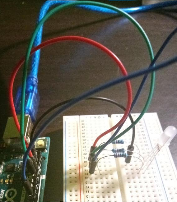
For the example project of this article we will do nothing but use the circuit already used to turn on a LED and of which we will modify the sketch to change the reference digital pin and add a couple of functions. For the list of components refer to this link.
The switchOn function
The switch on function with which we will gradually increase the brightness of the LED will perform a cycle using a counter that will be increased by one unit, starting from 0 to get to 255.
void turn on () {
  for (int i = 0; i <255; i ++) {
    analogWrite (LED_PIN, i);
    delay (30);
  }
}
Within the cycle we use analogWrite on the digital pin to create the effect of a continuous variation of values, while in reality we are just turning the LED on and off in rapid succession. We wait 30 milliseconds before moving on to the next iteration of the for loop to make sure that the fade is noticeable
Try varying the delay value to check the speed and perceptibility of the fading effect of the LED light.
The shutDown function
Mirroring the switch on function, the switch off function cycles backwards, starting from 255 and decreasing by one unit to 0, to create a fading effect when the LED is switched off.
void turn off () {
  // wait for a second
  for (int i = 254; i> = 0; i--) {
    analogWrite (LED_PIN, i);
    delay (30);
  }
}
The complete sketch
Here is the entire listing to test PWM modulation with Arduino:
#define LED_PIN 11

// the setup function runs once when you press reset or power the board
void setup () {
  Serial.begin (9600);
  pinMode (LED_PIN, OUTPUT);
}

void turnOn () {
  for (int i = 0; i <255; i ++) {
    analogWrite (LED_PIN, i);
    delay (30);
  }
}

void turnOff () {
  // wait for a second
  for (int i = 254; i> = 0; i--) {
    analogWrite (LED_PIN, i);
    delay (30);
  }
}
// the loop function runs over and over again forever
void loop () {

  // put your main code here, to run repeatedly:
  if (Serial.available ())
  {
    int state = Serial.read ();

    switch (state)
    {
      case 'A':

        Serial.println ("Start power fade");
        lightOn();
        Serial.println ("Led on");
        break;

      case 'S':

        Serial.println ("Start power off fade");
        switchOff();

        Serial.println ("Led off");
        break;

      default:
        Serial.println ("Command not recognized");
        break;
    }

    delay (300);
  }

}
At the beginning of the source code, the LED_PIN constant associated with Arduino pin 11 pwm is defined. Subsequently, in the setup function, we set the baud rate for the serial communication and the pin in OUTPUT mode.
In the Arduino loop, we check the input value on the serial monitor, according to which the turn on function or the turn off function is called.
Try to modify the sketch code in the same way to manage the RGB LED creating a fade effect.
Conclusion
In this article we have seen how easy it is with Arduino and the PWM digital pins that it makes available to us, gradually turn a LED on and off, creating a fading effect. We have examined what the pulse width modulation technique consists of and how it is able to deceive the human eye by varying the interval in which a digital pin remains in the ON or OF state