Now that we have acquired the basics of programming with Arduino and some basic notions of electronics, we are ready to put the pieces together and create a first prototype with a bit of coding and a bit of hardware. Let’s review the required components immediately.
List of components
For our first real Arduino project we will need:
- An Arduino Uno board
- A breadboard
- two jumper cables (with male-male connectors)
- a small piece of twisted pair (also called “bridge” in jargon)
- one led
- a resistance of at least 220 ohms
- a usb cable to connect Arduino to the pc
The jumper cables
To make the connection between Arduino and the LED easier we will use two jumper cables, ideal for prototyping on breadbord. On the market there are various lengths and equipped with various types of connectors; in our case, two of about 11 cm long with male-male connectors will be enough.
The twisted pair
To connect components that are very close to each other on the breadboard, it is very useful to use small sections of the cables obtained from any telephone pair, after having properly stripped them. You can fold them if necessary for insertion into the breadborad holes
The led
The led (light emitting diod) is a component based on a semiconductor material that allows the electric current to flow in one direction only. The LEDs frequently used in Arduino prototypes are of the “pass-through” type, in the sense that they are connected to a circuit by passing the terminals from one side of the board to the other; precisely for this reason they have terminals of a certain length (respectively called anode, which connects to the positive pole, and cathode, to be connected to the negative one). The most common LEDs of this type are designed to emit red, yellow or green light and have a bias voltage of about 2 V and can support a maximum current of 30 mA.
The resistance
To avoid burning the LED, we will use a resistor which has the task of limiting the passage of current. A resistor usually looks like a kind of cylinder covered with colored strips, from which two connectors come out. The colored strips, four or five in number, are intended to indicate the resistance value, which according to their combination, must be recalculated in ohms. The values must be read from left to right; each color corresponds to a number, except for the rightmost strip which indicates the number of zeros to add. The following table will help us to decode the values of a resistor:
| Colour | Value | Zeros |
|---|---|---|
| Black | 0 | – |
| Brown | 1 | 0 |
| Red | 2 | 00 |
| Orange | 3 | 000 |
| Yellow | 4 | 0000 |
| Green | 5 | 00000 |
| Blue | 6 | 000000 |
| Violet | 7 | 0000000 |
| Gray | 8 | 00000000 |
| White | 9 | 000000000 |
In addition to these values, the tolerance is also indicated with three other options:
- gold, ± 5% tolerance
- silver, ± 10% tolerance
- no color, ± 20% tolerance
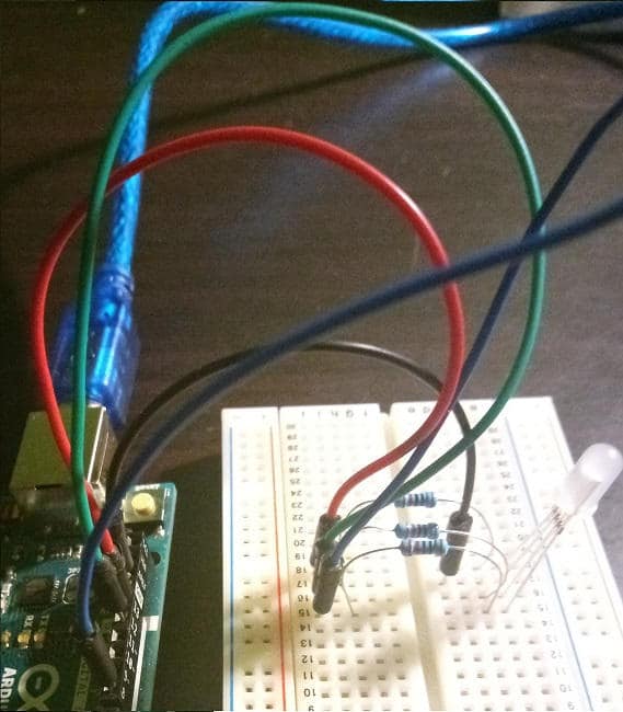
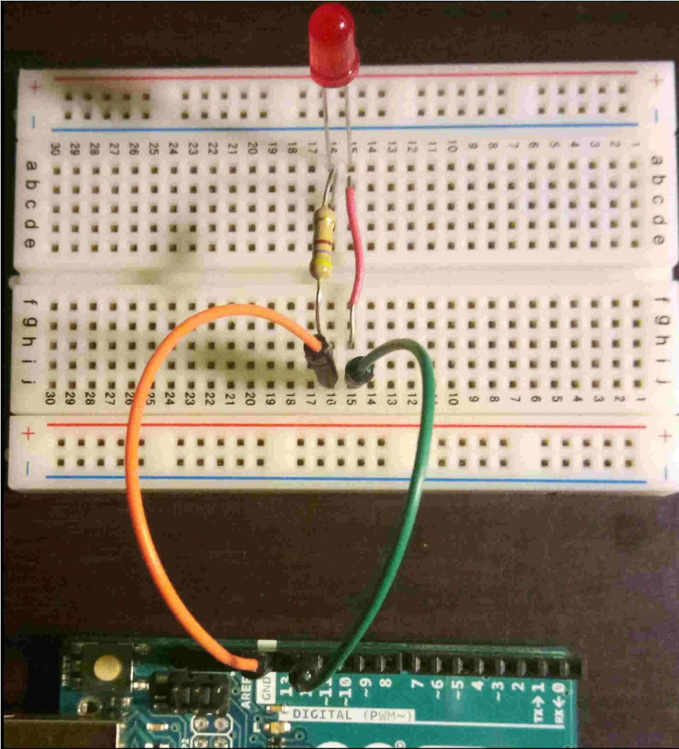
Taking for example the resistance as in the photo of the circuit below, we have:
- a yellow stripe: 4
- a purple stripe: 7
- a brown stripe: 0
- a golden stripe: ± 5%
Putting the values together we have 47 to which to add a zero, therefore 470 ohm, with ± 5% of tolerance. In this case, the brown was the last strip on the right before the one indicating the tolerance value.
A form for calculating the value of a resistance
If you have already obtained a certain number of resistors, try to figure out their value in ohms by yourself and then check the result using the form below
The breadboard
The breadboard looks like a rectangular plastic panel, covered with holes divided into rows and columns (marked by numbers and letters). Inside the metal tracks connect the columns, allowing us to create circuits simply by inserting connectors in the holes corresponding to the electrical lines that we want to connect. In the circuit photo below, all the holes in column 15 from row a to row j are connected, as well as for column 16. The breadboard used in the photo also has two other groups of holes, top and bottom, which are instead connected horizontally.
Creation of the circuit to turn on the led with Arduino
To create the led lighting circuit, we proceed (as in the photo below), as follows:
- We connect a jumper cable to Arduino digital pin 12 (you can find the digital pins easily thanks to the "DIGITAL" label, in particular pin 12 is located near the pin marked as GND and pin 13)
- We connect the jumper cable already connected to pin 12 to the hole located along column 15 of row j of the breadboard
- We connect a jumper to the GND pin
- Connect the other end of the cable connected to pin GND to the hole corresponding to column 16 and to row j of the breadbord
- We insert the two poles of the resistance in two holes of the column 16 of the breadboard
- We do the same with the bridge but at column 15
- We insert the long terminal of the led in hole 15 and the short one in hole 16 of row a of the breadboard
- We connect Arduino to the pc via the usb cable
The program to turn on the led with Arduino
The program that we will load on Arduino, after having set the serial communication and the pin connected to the led, will remain waiting for input; by typing the character 'A' on the serial monitor, the digitalWrite function will be executed which takes the pin and the voltage value to be set on the pin as input. In this case we use the HIGH constant to send 5 v to the pin, causing the led to light up. By inserting the 'S' character instead, the execution flow will position itself on the second case of the switch block, in which the constant LOW is passed to the digitalWrite function, causing the LED to switch off. The call to the delay function at the end of the if block delays the execution of the Arduino loop by 300 milliseconds. If any other character is entered, the default block writes on the serial that the command has not been recognized.
#define LED_PIN 12

void setup () {
   // put your setup code here, to run once:
   Serial.begin (9600);

   pinMode (LED_PIN, OUTPUT);
   Serial.println ("Waiting for a command ... (A - turns on the led; B - turns off the led");
}

void loop () {
   // put your main code here, to run repeatedly:
   if (Serial.available ())
   {
     int state = Serial.read ();

     switch (state)
     {
       case 'A':
         digitalWrite (LED_PIN, HIGH);
         Serial.println ("Led on");
         break;

       case 'S':
         digitalWrite (LED_PIN, LOW);
         Serial.println ("Led off");
         break;

       default:
         Serial.println ("Command not recognized");
         break;
     }

     delay (300);
   }
}
We just have to try to enter an input on the serial monitor and experience what happens to the LED and what messages are printed on the monitor.
Try entering a long sequence of 'A' and 'S' at once and explaining their behavior.
Conclusions
In this article we have built a very simple and functional first circuit with Arduini, combining the coding knowledge acquired in previous tutorials and some basic notions of electronics. We made use of some commonly used components, essential in the construction of prototypes, such as the breadboard, resistors and LEDs. We also made sure to interact with the circuit via serial monitor command input. We will soon see other examples of circuits for Arduini assembled with other commonly used components such as sensors, RGB LEDs, displays, buzzers, motors, etc.