Unlike a common LED, which emits light of only one color, an RGB LED can emit three different types of light, red, yellow and blue (Red, Green, Blue as the acronym itself says). This type of diode lends itself to very interesting uses, since by combining different shades of red, yellow and blue, it can emit light of various colors. Try to imagine how many projects you could use it in (a robot, a toy, a home automation simulation, an alarm etc., all cases in which, based on certain events, a light of a certain color clearly denotes a particular state of the object).
In this article we will create a small prototype in which we will drive the RGB led with Arduino, using the random function to generate random colors at each cycle of the execution loop.
Colors in the RGB system
In the RGB system, each color gradation can vary from a value ranging from 0 to 255: the value 0 represents the total absence of color, while the value 255 indicates its maximum saturation.
| RGB Value | Colour |
|---|---|
| 255, 0, 0 | Red |
| 0, 255, 0 | Green |
| 0, 0, 255 | Blue |
| 255, 255, 255 | White |
| 0, 0, 0 | Black |
| 255, 255, 0 | Yellow |
| 255, 165, 0 | Orange |
| 127, 127, 127 | Grey |
The table above lists some examples of RGB coding to which a specific color corresponds. Since each triplet can contain, we repeat, values between 0 and 255, we can obtain 256 * 256 * 256 possible combinations of colors (16777216 in total).
List of components
To create our prototype to drive the RGB led with Arduino, we will need:
- a common cathode RGB led
- 3 resistors of 220 ohm
- a breadboard
- 4 jumper cables
- an Arduino board
- a usb cable to connect Arduino to the pc
The RGB led
An RGB LED is made up of three different LEDs inside, one for each of the three colors: red, green and blue.
It has four connectors and there are two types:
- shared anode, in which the anode uses the 5 V voltage on the common pin of the three LEDs
- shared cathode, where the common pin is connected to ground
As we have seen from the list of components we will use the second type of RGB LED, of which we will connect the cathode to the ground pin (GND) of the Arduino (in the photo below, the cathode is easily recognizable by the greater length compared to the other three connectors) .

The circuit to control the RGB led with Arduino
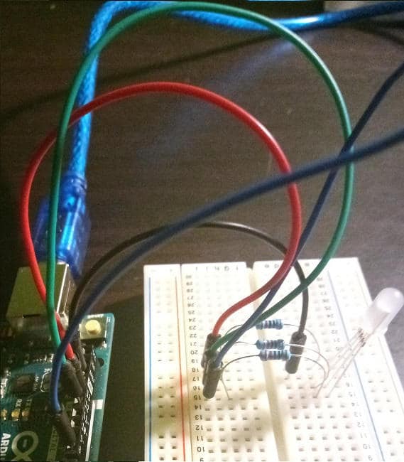
As you can see from the photo above, the red LED connector has been connected in series with a resistor at pin 13 of Arduino; immediately after the common cathode to pin GND, while the green connector was connected to pin 12 and, finally, the blue to pin 8. To better highlight the connections, I used jumper cables of the color corresponding to that of each pin of the led.
The resistors, as usual, have the task of limiting the flow of current to the LED; if you prefer it to emit less light, use higher value resistors.
If necessary, refer to the resistance calculation form to find the combination of colored strips you prefer.
The sketch to manage the RGB led
Let’s see the code of our project immediately:
// red pin
#define RED 13
// pin green color
#define GREEN 12
// pin blue color
#define BLUE 8
void setup () {
// initialization of serial communication
Serial.begin (9600);
// pin led colors in output mode
pinMode (RED, OUTPUT);
pinMode (GREEN, OUTPUT);
pinMode (BLUE, OUTPUT);
// setting the pin voltage to LOW
digitalWrite (RED, LOW);
digitalWrite (GREEN, LOW);
digitalWrite (BLUE, LOW);
}
void loop () {
// random value for the red pin
const int randRosso = random (1, 255);
// random value for the green pin
const int randVerde = random (1, 255);
// random value for the blue pin
const int randBlu = random (1, 255);
// red ignition
analogWrite (RED, randRosso);
// green light
analogWrite (GREEN, randVerde);
// blue ignition
analogWrite (BLU, randBlu);
// send the values assigned to the pins to the serial monitor
Serial.print ("RED:");
Serial.print (randRosso);
Serial.print ("- GREEN:");
Serial.print (randVerde);
Serial.print ("- BLUE:");
Serial.println (randBlu);
// rgb led on for two seconds
delay(2000);
}By means of the preprocessor directives, the constants of the pins to which the LED connectors are connected are defined; subsequently, in the setup function of Arduino, after having initialized the serial communication, the pins are set to zero volts.
In the loop, the random function generates random values between 0 and 255 for the constants that will create the RGB triplet to be sent to the LED. The first parameter passed to random is precisely the minimum value 0 from which to generate random numbers, while the second is the maximum value (255).
Once we have the three random values, we pass them to the analogWrite function to send the analog signal to each pin. Unlike digitalWrite, which manages the two states LOW and HIGH, analogWrite can send different gradations of values to the Arduino pins. In this case it is very useful for varying the colors of the LED: at each iteration a random color will be obtained, which will be maintained for 2 seconds by calling the delay function.
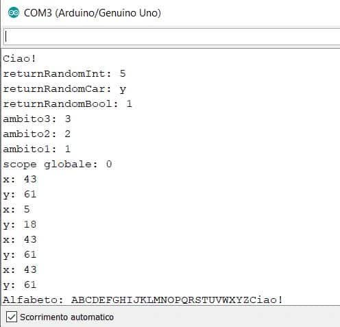
Finally, the blue, green and red values are printed on the serial monitor. Here is an example of output:
RED: 44 - GREEN: 72 - BLUE: 30
RED: 239 - GREEN: 221 - BLUE: 123
RED: 61 - GREEN: 99 - BLUE: 44
RED: 170 - GREEN: 175 - BLUE: 214
RED: 127 - GREEN: 113 - BLUE: 242
RED: 14 - GREEN: 222 - BLUE: 140
RED: 249 - GREEN: 101 - BLUE: 250
RED: 204 - GREEN: 72 - BLUE: 62
RED: 99 - GREEN: 172 - BLUE: 226
RED: 131 - GREEN: 35 - BLUE: 24
RED: 36 - GREEN: 77 - BLUE: 213What happens if we replace the calls to analogWrite with digitalWrite?
Try to print the values in rgb format on the serial, eg. rgb (36, 77, 213), copy the string and paste it into this color picker; what color do you get? Also try to check if the light emitted by the LED corresponds to the color identified by the color picker, commenting on the calls to the random function and assigning the values of a triplet generated on the monitor. The more willing can try adding a button to turn on the RGB LED, combining the code just presented with that of a previous article.
Conclusion
In this article we have created a prototype on breadboard with Arduino to control an RGB LED. The project turned out to be very instructive, because, in addition to showing us how an RGB LED differs from a common LED, it allowed us both to obtain multiple color combinations by mixing red, green and blue, and to introduce the generation of numbers. random. Furthermore, we could also appreciate the difference between the analogWrite and digitalWrite function.