Unlike common resistors, a photoresistor (or photocell, but also LDR – Light Dependent Resistor) exhibits a high resistance in the absence of light (roughly 1 mega ohm) and a weaker resistance that varies according to the brightness level to which it is exposed (about 100 ohms). Responsible for these resistance fluctuations depending on the amount of light is the semiconductor material with which it is made, a particular chemical compound deposited on the surface. To measure the actual values it is possible to use a digital meter (to the use of which I will dedicate a separate article).
There are many and many applications of an LDR, but the most common use made of it, especially in projects for beginners, is the measurement of light intensity in a typical weather station.
In this article we will create a simple circuit that will allow us to read the values of a photoresistor and display them on the serial monitor. We will also see how to calibrate the LDR with subsequent adjustments. But not before having clarified the difference between digital and analog quantities, since we will read the resistance fluctuations of the photocell from an Arduino digital pin.
Digital and analogue quantities
So far we have used the Arduino digital pins to send high or low voltage values in a circuit, via the digitalWrite function and the HIGH and LOW constants, practically obeying the on-off logic. However, when we had to manage an RGB LED, having to send different variations of red, green and blue to the LED pedestals, we had to use the analogWrite function to which RGB values between zero and 255 can be passed, thus managing to manage a larger scale. compared to HIGH and LOW.
The intensity of light, like that of RGB colors and like all quantities present in nature, is an analogue type quantity, as there is an analogy between the actual physical quantities it represents. The changes in air pressure produced by a sound, for example, can produce corresponding variations in the electric current thanks to the resonance of the membrane of a microphone; these current fluctuations represent the variations of natural sound, constituting an analog electrical signal. Since an analog signal is a continuous quantity, in order to be measured by a digital device such as a computer, it must first be converted into numerical sequences, where each number represents the change in signal intensity at a given instant of time, this which in jargon is called sampling.
Arduino is able to read the analog signals of a sensor through the analog pins, clearly visible on the card with the “Analog in” label. Their numbering in Arduino goes from 0 to 5 and each pin is marked with the letter A, which corresponds to a constant in the standard library (so in a sketch we will use the constants A0, A1, A2, A3, A4, A5 respectively). The readable values from these pins range from 0 to 1023.
Now let’s see in practice how to create the management circuit of a photoresistor with Arduino.
Parts list and test circuit
To create the circuit we will need:
- a photoresistor
- a 1k ohm resistor
- a breadboard
- three jumper cables (possibly of different colors)
- an Arduino board
- a usb cable to connect Arduino to the pc
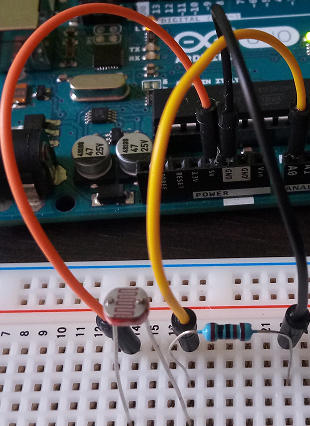
As you can see in the photo, we connect one pin of the photoresistor to the Arduino 5v power supply pin, while the other pin of the sensor is connected in series to the 1k ohm resistor and to the digital pin A0. The other leg of the resistor is connected to the Arduino GND ground pin. We will discuss this type of circuits in jargon called voltage dividers later.
The sketch to measure the light intensity with Arduino and the photoresistor
The sketch is very simple. Let’s see it right away:
#define LDR_PIN A0

void setup () {
  // put your setup code here, to run once:
  Serial.begin (9600);
}

void loop () {

  float luminosity = luminosity measure ();

  Serial.print ("Brightness:");
  Serial.println (brightness);
  delay (1000);
}

float measureLuminosity () {
  int value_ldr = analogRead (LDR_PIN);
  float converted_ldr_val = map (lldr_value, 20, 1005, 0, 100);

  return val_ldr_converted;
}
We immediately define the constant LDR_PIN connected to pin A0 and, in the setup function, we initialize the serial communication as usual. In the loop we insert an invocation to the measureLuminosity function (which we will analyze shortly), to assign its return value to the brightness variable, which we then print on the serial monitor using Serial.println.
The function of converting the photoresistor values acquired by the Arduino pin A0
After the Arduino loop function, we have defined the measureLuminosity function which returns a value of type float. After reading the input value from pin A0 via analogRead, we assign it to a convenient variable, value_ldr, which we pass to the map function of the standard library, to convert the values between 0 and 1023 processed by Arduino to a percentage scale from 0 to 100. Finally, the value obtained is returned to the caller.
The map function, as the name implies, has the task of remapping a range of values (in this case 0 – 1023) to another range (0 – 100). It takes in five parameters, the current value, the lowest and highest value of the starting range and the values of the final range.
Calibration of the brightness sensor
You will notice that I passed the values 20 and 1005 to the map function which I got through subsequent adjustments. Calibrate your sketch by replacing the two starting range parameters with 0 and 1023; then start reading the values on the serial monitor, first without manipulating the photoresistor, then, alternatively, covering it completely and lighting it (I used the smartphone flashlight). If the minimum value indicating darkness does not reach zero, add some units to the second parameter of the map, and subtract from the third if the maximum brightness does not reach 100. In this way you will have a slightly higher degree of accuracy.
Here are the values printed on my serial monitor during calibration:
Brightness: 33.00
Brightness: 32.00
Brightness: 8.00
Brightness: 7.00
Brightness: 7.00
Brightness: 6.00
Brightness: 85.00
Brightness: 97.00
Brightness: 98.00
Conclusions
We have seen how Arduino can receive analog inputs, what is the difference between analog and digital quantities and how we can use the values processed by Arduino to make analog measurements in our projects. We have created a practical example of a circuit with a photoresistor to apply these notions to measuring brightness levels with Arduino. Finally, we encapsulated the code for reading and converting the LDR values into a potentially reusable function. In future articles we will do the same with other types of sensors.